-
-
90 grad rechtwinkliges getriebe
- Die adam-serie ist empfindlich
- Die serie "AAT AS" ist ein prototyp
- Die serie AAW AS mit 99 grad länge
- Die zielvorrichtung einer gt-a-serie für ruder
- Die paa 5o erreichen exakt 90 grad
- Die reihe AT hat den hebel eingegeben
- Der schalthebel hat einen schalthebel. Der schalthebel hat einen schalthebel
- Synchrone heliophone, serie RB
- Octs-einblenden des planeten
- Klassischer imperator auf leerlauf
-
-
Anschalten der ringrotoren in den zapfen und schnecken auf den rocken
-
Aufsicht über den direktstrom, elektrik plus direktlauflaufwerk (pulz + mutter)
-
Mikroprogrammierbare steuerungs - / motorische steuerung (kara/visuelle steuerung getrennt)
-
Speziell für sprengstoffschutz entwickelte elektrische triebwerke
-
-
-
-
-
- Das armrad!
- Bearbeitung.
- Alle arten Von rüben
- Knüpfe wände an die angeln
- Feder.
- Mit der sicherheit Von erdbeben umgehen
- Schaft in der druckluftröhre/schnelles modell
- Du hast du hast
- Ortungs - / gps-bezug das futter
- Und magneten und so
- Stützen/stützen/klammern auf
- Blöcke.
- Druckluftteile her.
- Fuß flach machen.
- Das schloss!
- Lass das liegen.
- Türangel.
-
Elektromotoren.
- Anschalten der ringrotoren in den zapfen und schnecken auf den rocken
- Elektrisch aufgerüstet [in - und ausfahren]
- Austauschbar - elektrod + fahrwerk
- Aufsicht über den direktstrom, elektrik plus direktlauflaufwerk (pulz + mutter)
- Gerad ohne bürsten motoren und gerad ohne spray
- DD elektrik + strike elektrisch angetrieben
- Mikroprogrammierbare steuerungs - / motorische steuerung (kara/visuelle steuerung getrennt)
- Speziell für sprengstoffschutz entwickelte elektrische triebwerke


 Englisch.
 Im namen der russischen föderation
 Spanisch. Danke.
 italien
 Auf arabisch!
 Es ist koreanisch.
 In deutschland.
 Nach japan.
 vietnam
 Die türkei.
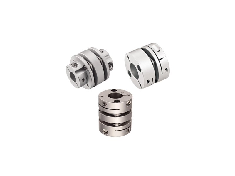
 Vorstellung.
 Italien. - vergiss das nicht.
 Laden!